Alignment
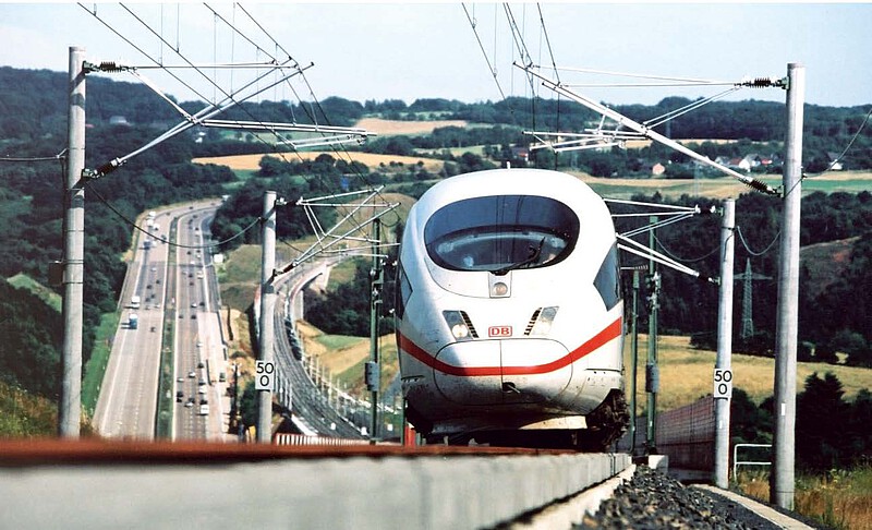
Trace refers to the railway track and its spatial location in the landscape. To find the optimum trace for new railway projects or existing lines, a variety of criteria, such as required travelling speed, timetable, topography and the associated costs, have to be taken into account.
The track design (alignment) follows the operating programme forecast for the time the line is put into service. In track curves, the cant to be installed (this is the difference in height between the outer and inner rail of the curve) is limited depending on the superstructure; in Germany, a maximum of 170 mm is permitted for slab track as a design basis. Similarly, the permissible cant deficiency for fast-moving trains and the permissible cant surplus (for slow-moving trains) are limited. Recommended values and limits can be found in EN 13803. This measure serves to limit the free lateral acceleration transverse to the superelevated track, which as a rule does not exceed 1 m/s².
If a line is also to be routed for freight trains, the maximum longitudinal gradient must be limited in such a way that the train hook limit load is not exceeded and these trains can also start on an uphill gradient and brake on the corresponding downhill gradient. For this reason, new mixed traffic lines can only be routed relatively flat: 12.5 ‰ as a standard value, a maximum of 20 ‰ if only "light" freight trains are to be considered. A longitudinal gradient of 12.5 ‰ corresponds to a height difference of 12.5 m over 1 km of track.
For lines intended only for suitably equipped passenger trains, higher longitudinal gradients can be allowed. According to TSI or EN 13803, a maximum of 35 ‰ is permissible, according to EBO even 40 ‰ for suburban trains and high-speed lines.
The low longitudinal gradient for lines suitable for cargo trains places special demands on the overcoming of height obstacles for the railway. In the early days of the railway, artificial length developments were used to bring the railway line up to the high tunnel mouths of crest tunnels or to the top of the pass. In contrast to roads, railways did not have the possibility to climb the mountain slopes with 180° hairpin curves; this is opposed by the deflection forces in the train and the poor curve mobility of the wheelsets, which glide through narrow curves more than they roll. Therefore, according to EBO, the curve radius on main lines should not be less than 300 m.
Recommended specialist literature:
Hansmann, Fabian; Nemetz, Wolfgang; Spoors, Richard, Keeping Track of Track Geometry
https://www.pmcmedia.com/en/all-titles/rail/428/keeping-track-of-track-geometry
Jänsch, Eberhard; Lang, Hans Peter; Nießen, Nils (Hrsg.), Handbuch Das System Bahn
https://www.pmcmedia.com/neuerscheinungen/427/handbuch-das-system-bahn?c=10
Wittenberg/von Lüpke/Zwanziger/Heinrichs (Hrsg.), Kommentar zur Eisenbahn-Bau- und Betriebsordnung (EBO)
https://www.pmcmedia.com/neuerscheinungen/422/kommentar-zur-eisenbahn-bau-und-betriebsordnung-ebo

