Taking bearings
The rapid development in the 19th century led to the construction of railways, canals and roads for the transport of raw materials and finished products. A good knowledge of geography and logistics was necessary for the planning of these cross-border traffic routes. The maps of that time contained details of the countryside, but there was no information on the heights of the various mountains, valleys, roads or lakes. There was no consistent and comprehensive system of height measurements. Every major city had its own local network of height points with a specified reference point. In Prussia it was decided in 1875 that all height measurements and points would be based on a standard zero point.
Some levels in the North Sea and the Baltic were available which had been used as a reference point in the last decade for differential levelling in Prussia. In 1879, a point on the old Berlin Observatory was specified as standard reference height and called the normal height point. Its height above the zero marks of the various levels was about 37 metres above sea level. Thus, the reference surface, which lies exactly 37.000 m below the normal height point, was called the normal zero. It is a devised level which agrees with the average height, of the water level of the North Sea and Baltic. The normal height point was the reference point for the already existing bench mark for the entire German Reich. Between the years 1912 and 1954, the German national height system was divided into different sections (geometric levelling). In the Federal Republic of Germany the normal zero height reference system (NN) of 1912 was still valid.
The height reference system introduced in 1953 zero height (HN), with the starting point of the Kronstädt level near St. Petersburg, was used until the end in the former GDR. The different elevation data between the FRG and the GDR showed differences of 12 cm to 16 cm. The survey offices of the old Federal countries decided in 1993, to replace the different height systems with a standard height reference system for the whole of Germany, called the German main height network (DHHN). On 1st January 2002, the new height reference system (DHHN) came into force in Germany.
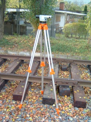
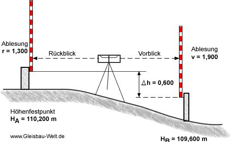
From a known measurement point (either from a levelling point or a point already associated with a levelling point) the difference in height to the new point is calculated and determined by forward and backwards sighting. This uses a horizontal measuring instrument, for example, a theodolite, which is set up between the known point (looking backwards) and the new point to be measured (looking forwards). A levelling staff is set up at each of the two points.
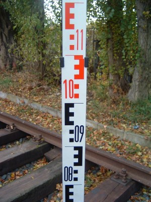
The height of the horizontal plane is read by means of the measuring device on both measuring staffs. The height difference between the two points can be obtained from the reading of both bars. The scale on the levelling staff can be read on the crosshairs of the theodolite. The scale shows centimetre fields. The staff can be read to within a millimetre at distances up to 25 m. The decimetre sections (0.1 - 4.0) are quantified. There are also measuring staffs with a length of 5 m.
Difference = rear view reading (r) - forward view reading (v)
Thus, the differences to all measuring points can be determined. As a check a second measurement should be made. If the measured values differ in height by more than 2 mm, the measurement should be repeated. The measuring staffs are a maximum of 5 m long, otherwise they can no longer be held still. This means that the measurable difference in height is approx. 4.9 m, i.e. in the case of larger height differences between two measuring points intermediate points must be selected. In order to counteract differences due to lengths of the staff, strong wind or different heights, so-called staff straighteners, are used. These are already pre-assembled or even set up at the side of the measuring staff. In this staff straightener there is a circular bubble.
A tested measuring instrument is the basic requirement for satisfactory measurements. Damage to the housing of the carrying case can lead to measurement errors.
You can find suitable specialist literature to the topic here:
The Basic Principles of Mechanised Track Maintenance
This book is dedicated to the many people involved in the day to day planning and performance of track maintenance activities. Providing a practical approach to everyday challenges in mechanised track maintenance, it is not just intended as a theoretical approach to the track system.
Railways aim at transporting people and freight safely, rapidly, regularly, comfortably and on time from one place to another. This book is directed to track infrastructure departments contributing to the above objective by ensuring the track infrastructure’s reliability, availability, maintainability and safety – denoted by the acronym RAMS. Regular, effective and affordable track maintenance enable RAMS to be achieved.


