Chain catenaries
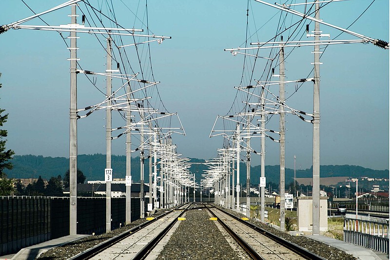
The overhead contact line system is the network for supplying electrically powered vehicles with electrical energy from the substations. Overhead contact lines have been continuously developed in line with the increasingly demanding tasks, so that the designs range from the simple overhead contact line (without suspension rope) for low operating speeds to the modern catenary overhead contact line for high-speed lines.
Because of their relatively simple construction and good electrical and mechanical properties, catenary systems are a tried and tested solution. The perfect interaction of overhead contact line and pantograph determines the reliability, operational safety, availability and quality of the power transmission to the traction units. The catenary system (contact wire and suspension cable) cannot be designed redundantly. The infrastructure manager must ensure the electrotechnical safety of persons and installations.
In EN 50122-1 and in the guidelines of the infrastructure managers, the overhead contact line area is defined as the limit that a broken overhead contact line does not normally exceed. The pantograph range specifies the limits that a live pantograph does not normally exceed, even in the event of a break or derailment.
For speeds of 300–400 km/h, more than 10 MW have to be transferred from the contact wire to the current collectors, which means that physical limits are reached. DC systems are only suitable to a limited extent for high-speed lines because the high power/currents place a very high load on the contact system between the contact wire and the pantograph. A drive power of 10 MW results in approx. 3500 A at 3 kV, approx. 700 A at 15 kV and approx. 400 A at 25 kV from the contact wire.
For direct current railways, therefore, catenary systems with double contact wires and current collectors with more than two contact strips are often necessary due to the high power requirement, while light catenary systems with one contact wire and current collectors with two contact strips are sufficient for alternating current railways.
Performance characteristics and specifications for the interoperability and contact behaviour of the contact line are mainly the geometry of the contact line, the mean contact force, the dynamic behaviour, the static criteria, the pantograph spacing in multiple traction and the sufficient power provision and current carrying capacity. The wear on the contact strips and the contact wire increases with the running speed, with the contact force and with the current load between the pantograph and the contact wire.
The relevant technical specifications for overhead contact line systems for planning, dimensioning, execution and assessment are fundamentally defined in the TSIs and, in addition, in the ENs. The design of an overhead contact line must be certified by a simulation system validated according to EN 50318 and by measurement according to EN 50317 with interoperable measuring current collectors.
For a free, interoperable network access to the infrastructure, the following geometric parameters, e.g., are decisive, such as boundary line, infrastructure clearance, contact wire height above SOK, permissible longitudinal contact wire inclination, permissible horizontal deflection of the contact wire from the track centre line and space for the lifting of the side support at the support point.
The structure gauge and clearances for all types of vehicles running on the line according to ENE TSI, LOC&PAS TSI and INFRA TSI shall be taken into account. The overhead contact line shall be designed for pantographs with the rocker geometry specified in the LOC&PAS TSI.
The overhead contact line system shall transmit the power to the traction units under constant electrical and mechanical contact without disturbances in all speed ranges and reliable power transfer shall be ensured even at standstill. Additional tasks of overhead contact lines are the transfer and regeneration of braking energy from the vehicles to the substations or the forwarding to other trains and the supply of auxiliary consumers (point heating systems, train preheating systems, etc.).
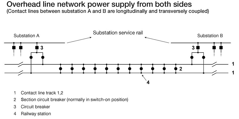
The electrical performance depends, on the one hand, on a sufficient and stable traction current supply and, on the other hand, on the transmission capacity of the overhead contact line system. In special cases, the overhead contact line system can also be fed directly from railway power stations or converter stations.
Components of overhead contact line systems
Overhead contact lines include contact wires, suspension wires, Y-beams, return current ropes, earth wires, (cables), feeder wires, booster wires and negative feeders for two-phase or multi-voltage systems, booster circuits and support structures for fixing, lateral guiding and insulating the conductors.
Explanations of the components:
- Feeder lines are electrical connection lines between switchgear and overhead contact line, laid on their own masts, on catenary masts or other support points as overhead lines or as cables.
- Reinforcement lines are overhead lines or cables laid parallel to the overhead contact line. They increase the usable line cross-section and thus improve the current-carrying capacity as well as the voltage quality. They are connected to the overhead line at certain intervals.
- Bypass lines are used to bridge overhead line sections that can be switched off in order to supply subsequent feeder sections.
- Return lines ("railway earthing") return the railway return current to the feeding substations in the event of operation and faults and also have the task of avoiding impermissible fault and contact voltages. Return lines should, if possible, draw off a large part of the traction return current from the rails.
Recommended specialist books:
Irsigler, Manfred, Systemtechnik von HGV-Oberleitungen
https://www.pmcmedia.com/neuerscheinungen/424/systemtechnik-von-hgv-oberleitungen?c=5


