Running surface of the turnout
Conventional turnouts can be divided in terms of their structure into three main parts:
- crossing and check rail
- tongue device
- closure rails
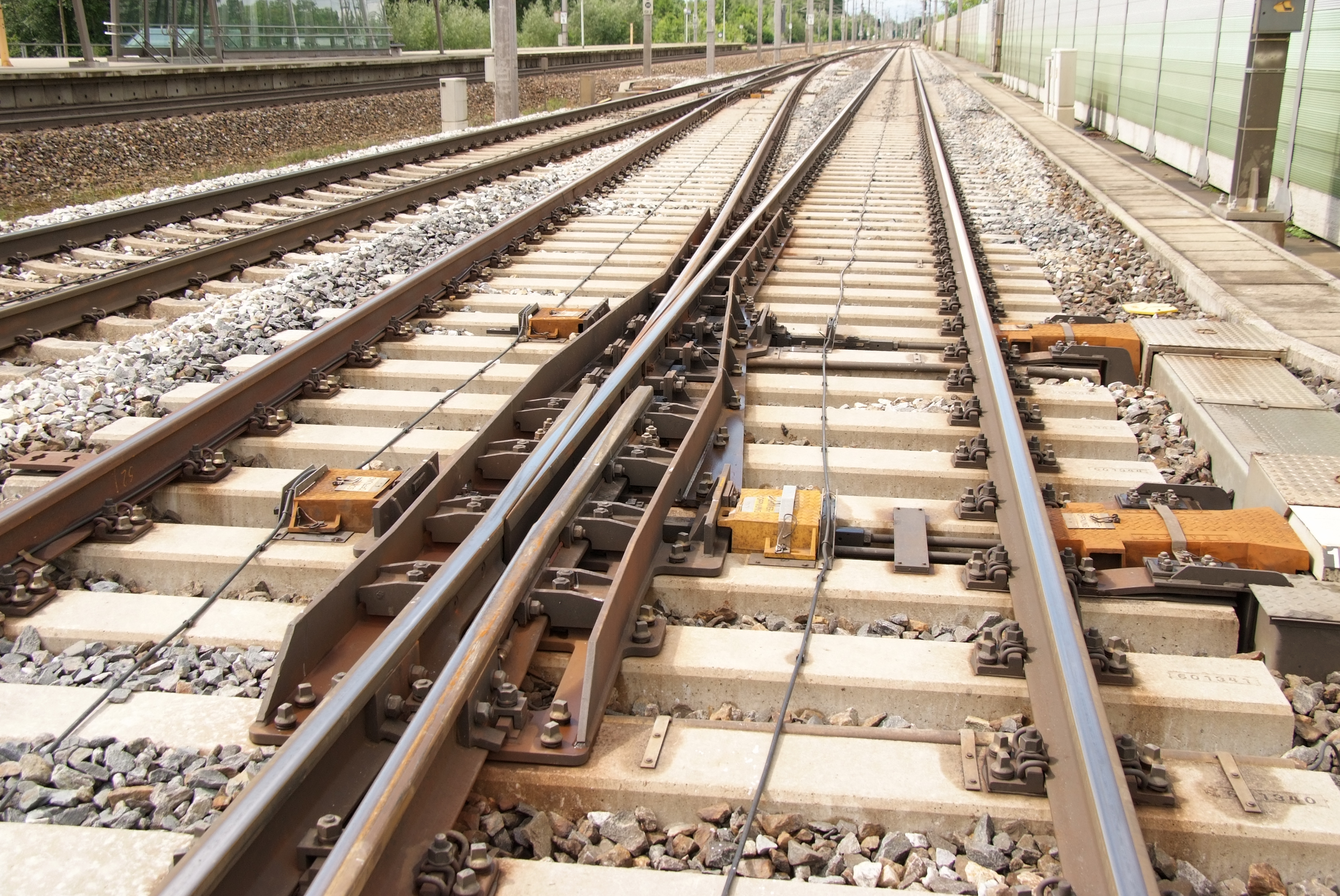
Crossing and check rail
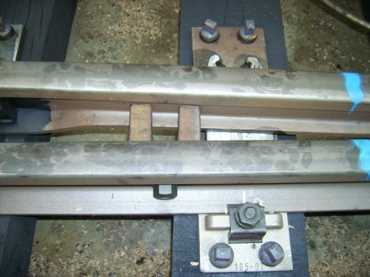
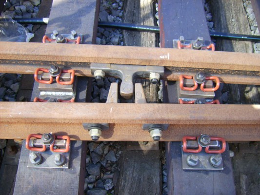
The simple crossing is made up of the crossing nose and two wing rails.
In order to enter the branch, the vehicle must cross the straight rail. Therefore it is necessary to break the running edge between crossing nose and closure rail. This produces crossing gaps where the wheel is not guided by the flange. As a compensation for the breaks in the track guidance a check rail is fitted on the opposite rail which prevents incorrect guidance. Check rails merely take over the guiding task while the load transfer is always done by the rail.
The interruption in the running edge increases the impact load for the track components and increases the noise emissions when a train runs over it.
The two wing rails form the continuation of the closure rail. In order to provide a passage for the wheelset, they are bent sideways.
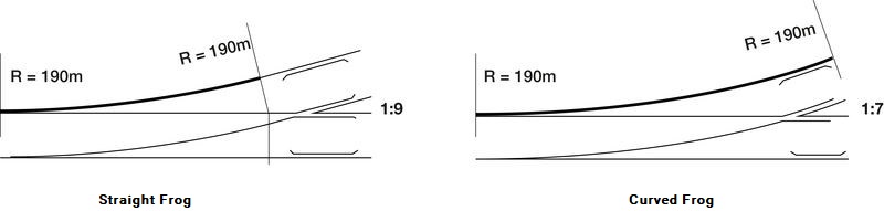
Depending on the selected branch radius, the end of the curve of the branch track comes before or after the crossing. If the curve ends before the crossing, one speaks of a straight crossing. If the crossing lies in the curve, it must be adapted to the curvature in the diverging track. Then it is referred to as a curved crossing.
Depending on the number of running edge breaks, a distinction is made between single, double and multi-part crossings. Double crossings are installed in crossings and diamond crossings with slips. Another distinguishing feature is the design[1]:
- rail crossings
- sectional crossings
- monoblock crossings
- swing nose crossings
Sectional crossings are a compact design for higher loadings. They consist of a nose block or a welded central block and can withstand higher loads. Monoblock crossings are made of manganese steel by casting, which is more wear resistant but places particular requirements on the welding technology. In the past, crossings made of cast steel were used. These are considered technically obsolete today.
In general, turnouts with rigid crossings are used, especially for very simple turnouts with flat turnout inclinations.
Through the use of swing nose crossings, the load on the whole system can be reduced. There are different types. The design with spring-loaded movable tips has proved to be effective over many years. The movement of the crossing creates a continuous running surface equivalent to the tongue device.
© Plasser & Theurer
Switch rail device
The tongue device allows the vehicle to change direction, either to run on the main line or on the branch line.
The main components are two tongues and two stock rails. In pairs, depending on the location, either the stock rail or the tongue rail is curved in order to allow the chosen direction to be taken. This is done by the movable tongue parts, which, together with the fixed stock rails, allow the train to travel depending on their position on the different turnout branches.
In theory, the tip of the tongue begins (tongue toe) at the start of the turnout with a width of 0 mm. Such a weakened profile would not withstand the loads, so the tongue is displaced and begins with a width of about 5 mm.[2]
The flange is guided by the tongue rail in the desired direction, while the vertical forces are taken as before on the stock rail. The asymmetric rail profile of the tongue is guided up to a width of 38 mm below the head of the stock rail, only from this width can the tongue accept vertical forces.[3]
The height of the turnout tongue is significantly lower than that of the stock rail. This is necessary in order to switch the tongue on the sliding chairs to the desired direction. In order to reduce the friction between the sliding chairs and the tongue, they must be lubricated at regular intervals. The lubricant is subject to all weather conditions. To reduce friction and thus to reduce the necessary maintenance of the sliding bearings tongue rollers are sometimes used in the slide chairs.
By displacing the tip of the tongue from the start of the turnout the angle of incidence of the wheel flange on the tongue is given by the tangent to the diverging curve. The guiding forces on the tip of the tongue are transferred directly to the stock rail by the contact of the tongue. Afterwards, the force is transferred over horizontal force locked couplings (support cleats) between tongue rail and stock rail.
© Thorsten Schaeffer
In order to minimise possible longitudinal movements of the tongue rail due to temperature influences, a rail anchor should be fitted. The tongue is kept in the desired position by different actuating devices and fixed. In this end position the tongue rail must be either form-locked to the stock rail or leave enough space for a groove to pass through in order to avoid the back of the wheel touching. The transition between the tongue root and closure rail is specially done in order to minimize the necessary switching force. Today there are two design principles:
- pring tongue
- spring rail tongue
© Thorsten Schaeffer
In the spring tongue the transition between the tongue rail and standard profile is in the back rigid immovable part of the tongue. The forging of the regular profile can be entirely protected with the rail fastening systems. In the area of spring point, the rail foot can be milled to a length of 1.50 m, which further reduces the switching resistance.
In contrast to this, in the spring rail tongue the forging to the standard rail profile is still done on the moving part of the tongue. Then the tongue is welded with the standard rail and additionally secured with safety straps.
Tongue rails are no longer designed as a purely circular curve, especially for high-speed trains, but as parabolas (parabolic tongue).
Closure rails
The closure rails - unmachined standard rails - guide the wheelset between the tongue and the crossing. In principle, individual support point designs are used to attach the rails to the continuous sleepers. If there is not enough space (especially in the area of the tongue and the crossing), special fasteners are used to secure two rails to the sleeper.
You can find suitable specialist literature about the topic here:
The Basic Principles of Mechanised Track Maintenance

This book is dedicated to the many people involved in the day to day planning and performance of track maintenance activities. Providing a practical approach to everyday challenges in mechanised track maintenance, it is not just intended as a theoretical approach to the track system.
Railways aim at transporting people and freight safely, rapidly, regularly, comfortably and on time from one place to another. This book is directed to track infrastructure departments contributing to the above objective by ensuring the track infrastructure’s reliability, availability, maintainability and safety – denoted by the acronym RAMS. Regular, effective and affordable track maintenance enable RAMS to be achieved.
Best Practice in Track Maintenance, Vol 1 - Infrastructure Management
Infrastructure Management Volume 1 looks at aspects of infrastructure management with particular reference to the single European railway area. Based on best-practice examples from Central Europe, measures for the targeted retrofitting and improvement of the infrastructure maintenance of the existing network are presented. In many cases, infrastructure operators are faced with a generational change, which accelerates the process. Modern information and communication technology can simplify the comprehension and presentation of complex contexts. Modified approaches to asset management and life-cycle management enable implementation of the "transparent permanent way" or the "railway 4.0".
- [1] Freystein, H.; Muncke, M.; Schollmeier, P.: Handbuch Entwerfen von Bahnanlagen. Regelwerke, Planfeststellung, Bau, Betrieb, Instandhaltung. Eurailpress, Hamburg, 2015.
- [2] Matthews, V.: Bahnbau. Mit 60 Tabellen. Teubner, Wiesbaden, 2007.
- [3] Fendrich, L.; Fengler, W.: Handbuch Eisenbahninfrastruktur. Springer, Berlin, 2013.