Concepts for turnouts
The term turnouts, includes classical turnouts, crossings and diamond crossings with slips. In addition to the traditional geometric parameters of main line track, for the turnout, gauging parameters, the radius of the diverging line and the turnout inclination are of importance.
Turnout inclination
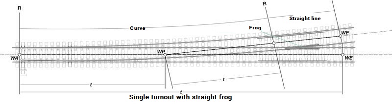
Turnouts can be distinguished by their basic shape and are clearly limited in their extent by the start and end of the turnout. The start of the turnout is the tangent point of the diverging track on the main line. The end of the turnout is described as that point at which both rails (the main line and the diverging line) are so far apart that welding or fish-plating is possible. This point also allows the use of separate rail fastening systems and requires a space of at least 200 to 220 mm. The tangent at the turnout end points makes with the track axis of the main line the angle of the turnout. The tangent of this angle is also called the turnout inclination. The turnout inclination is given as the simplest possible break. Such a simplification is sometimes only possible if the constructive turnout is pushed further down the diverging line. This geometric turnout end is a fictional point and is designated as the designed end of the turnout.[1] The distance between the main and the diverging line is designated as the spreading dimension.
© Erwin Klotzinger
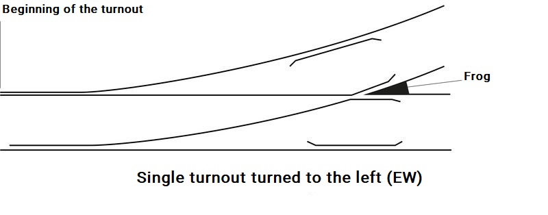
Running edge diagrams are often used to provide a simplified representation of the different types of turnouts. This gives a "Representation of a turnout in ground plan, where - by leaving out the constructive details - only the running edge of the running and guiding rail is drawn."[2]
© Erwin Klotzinger
Track guidance measurement
For safe operation the track guidance measurement in the turnout must be continually monitored and maintained. Essential for this are, among other things, the gauge, the flange groove, the distance apart of the guide rails and the check rail gauge. All values are measured with a track gauge normal to the track axis between 0 and 14 mm below the upper edge of the rail.
Track gauge: Distance between the two rail heads.
Flange groove: Distance between the guide rail and the running rail.
Check rail distance: Distance between the check rail and the associated wing rail.
Check rail gauge: Distance between the check rail and nose of the crossing.
Detailed descriptions can be seen in the European Standard EN 13232.
Branch radius
To choose the right radius of curvature for the branch, and thus the curvature of the diverging line, it is necessary to consider different points of view. On one hand, it is advisable from an operating point of view to choose a large radius in order to raise the permitted speed through the turnout.
On the other hand, larger radii lead to increased space requirements and increasing costs both in investment and also in maintenance. Depending on the permissible centrifugal acceleration, the required radius is:
R = apermissible*3.6²/Vpermissible²
or
Vpermissible = √(3.6 × Rpermissible × apermissible)
If it is assumed that the diverging branch is built without superelevation and a maximum lateral acceleration apermissible of 0.65 m/s² is authorised, the maximum speed is:
Vpermissible = 2.91 × √(R0)
The branch curve begins at the start of the turnout. Circular curves, basket arches or clothoids[1] are used for the shape. The latter are primarily used on high-speed lines, in order to reduce the resulting acceleration difference.
In addition to the turnout sleepers, the associated rail fastening systems and control devices and the running surface of the turnout forms the centre of the turnout. This consists of the tongue, the closure rails and the crossings with check rails and running rails. In conventional turnouts the wheelset has no guidance in the area of the gap at the nose of the crossing (between closure rail and crossing nose). Check rails in the main line and branch line, however, guarantee safe wheel guidance.[3]
[1] The term clothoid refers to a curve that begins at zero curvature at the straight section (the tangent) and increases linearly with its curve length.
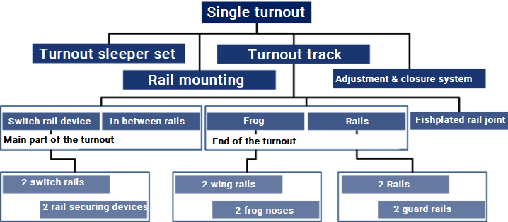
Parts of the turnout
A simple turnout contains the components shown below.
© Fabian Hansmann
Turnouts in the main line should be arranged in such a way that mutual interference can be avoided as far as possible. For the installation of safety facilities (e.g. axle counters, insulating joints, etc.) there should be a minimum distance between turnouts > 7 m.[1]
From the beginning to the end of the turnout the individual components of the running surface of the turnout are fixed to the crossing timbers. In this section the turnout assembly forms a fixed construction. For turnouts primarily reinforced concrete sleepers are used with and without elastic coating and hardwood sleepers. Turnouts are arranged differently[2]:
- perpendicular to the main line
- perpendicular to the bisector
- fan-shaped
The resulting partial rotation of the turnout places particular challenges on the correction of the position of the turnouts.
")
© Matthias Müller
")
© Matthias Müller
: single crossing turnout (EKW)")
© Matthias Müller
")
© Matthias Müller
")
© Matthias Müller
")
© Matthias Müller
")
© Matthias Müller
© Matthias Müller
© Matthias Müller
 single-sided double turnout (EinsDW)")
© Matthias Müller
© Matthias Müller
© Matthias Müller
")
© Matthias Müller
You can find suitable specialist literature to this topic here:
The Basic Principles of Mechanised Track Maintenance

This book is dedicated to the many people involved in the day to day planning and performance of track maintenance activities. Providing a practical approach to everyday challenges in mechanised track maintenance, it is not just intended as a theoretical approach to the track system.
Railways aim at transporting people and freight safely, rapidly, regularly, comfortably and on time from one place to another. This book is directed to track infrastructure departments contributing to the above objective by ensuring the track infrastructure’s reliability, availability, maintainability and safety – denoted by the acronym RAMS. Regular, effective and affordable track maintenance enable RAMS to be achieved.
Best Practice in Track Maintenance, Vol 1 - Infrastructure Management
Infrastructure Management Volume 1 looks at aspects of infrastructure management with particular reference to the single European railway area. Based on best-practice examples from Central Europe, measures for the targeted retrofitting and improvement of the infrastructure maintenance of the existing network are presented. In many cases, infrastructure operators are faced with a generational change, which accelerates the process. Modern information and communication technology can simplify the comprehension and presentation of complex contexts. Modified approaches to asset management and life-cycle management enable implementation of the "transparent permanent way" or the "railway 4.0".
- [1] Fendrich, L.; Fengler, W.: Handbuch Eisenbahninfrastruktur. Springer, Berlin, 2013.
- [2] Berg, G.; Henker, H.: Weichen. Eisenbahnbau. transpress Verl. f. Verkehrswesen, Berlin, 1978.
- [3] Freystein, H.; Muncke, M.; Schollmeier, P.: Handbuch Entwerfen von Bahnanlagen. Regelwerke, Planfeststellung, Bau, Betrieb, Instandhaltung. Eurailpress, Hamburg, 2015.