Lifting, lining and consolidating
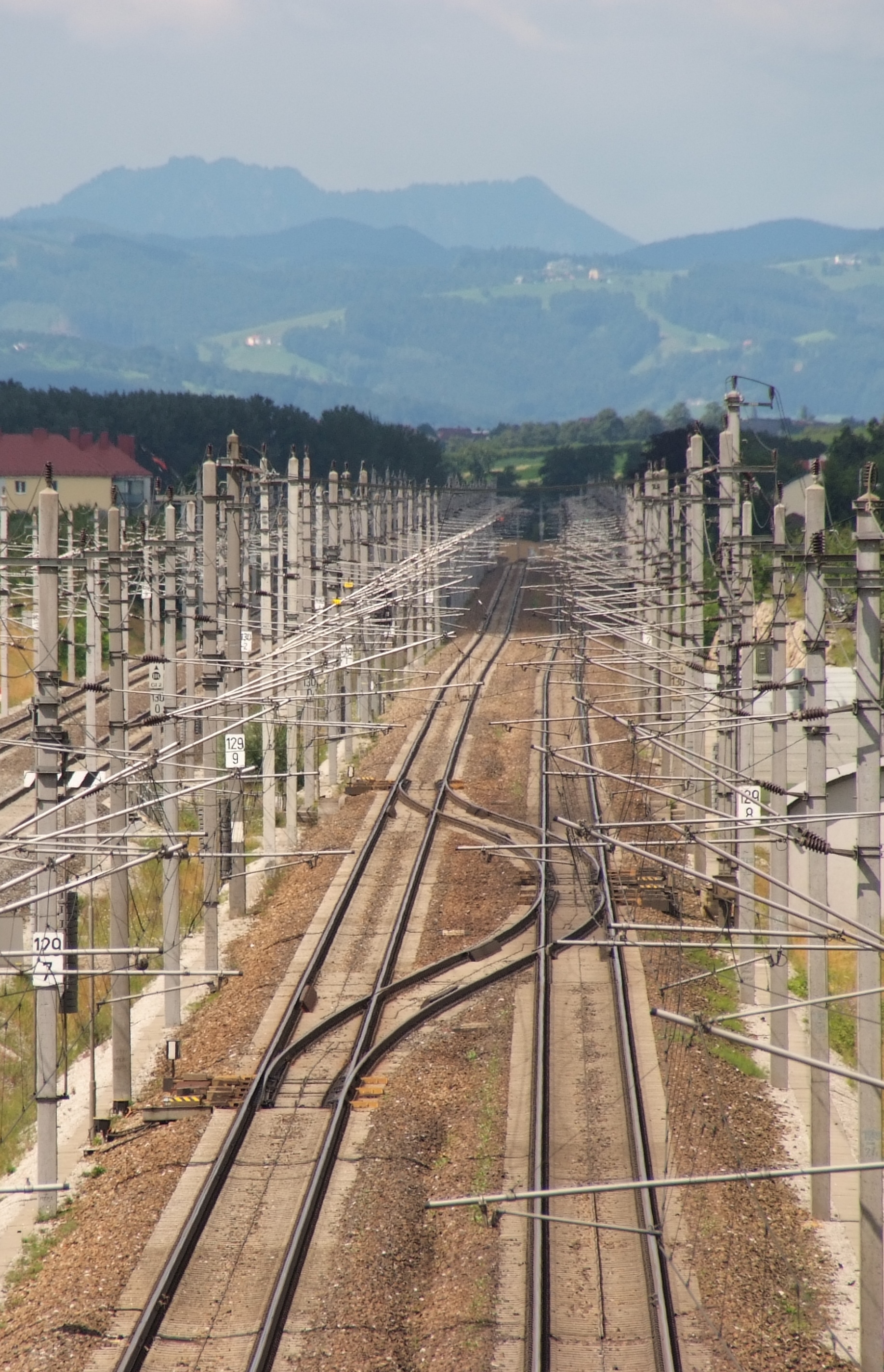
Ballasted track is still the most widely used design of permanent way worldwide. Ballast was originally chosen as the load distributing element due to its high availability, however, the demands on the system have increased significantly since then. Today ballast is far more than an indiscriminate pile of excavated material. Together with other components, it forms a highly active system. Clear chemical, geometric and physical reference values define the national requirements for the ballast. Over the useful life of the system these properties change and so does the overall behaviour.
The system flexes under the applied load. The resulting bending line makes it possible to distribute the loads on several sleepers and dissipate them. The load transfer, however, has its effect on the ballast. Due to different wear mechanisms in the ballast and in the subsoil a part of the settlement appears plastically. The result is track geometry faults, horizontal and/or vertical deviations from the desired track geometry (target geometry). At the latest after reaching the defined limits (EN 13848) the track geometry must be corrected, in order to allow the safe operation of the system. Track geometry faults significantly affect the riding of vehicles on the system. Comparable with bumps in the road, transport vehicles can compensate for this irregularity depending on their speed. If that does not work anymore, a derailment is the logical consequence. Railway Infrastructure Managers begin to take action to maintain the track ballast long before reaching this threshold. The reduction of the dynamic impact on the overall system, the restoration of the basic elastic properties, and the guarantee of the desired riding comfort are at the forefront of this. It is very important for the overall system, in particular, to prevent excessive formation of cavities and to create homogeneous sleeper support.
© Plasser & Theurer
Some time ago various firms designed special tamping machines for the mechanical correction of such track geometry faults. The first step in a proper correction of the track geometry is the determination of the desired lifting and lining values. Briefly the following procedures can be distinguished:
Compensation procedure without known route parameters (error reduction procedure)
Reduces the deviations of the existing track geometry.
Compensation procedure with known route parameters (error reduction procedure)
Reduces the deviation of the track geometry, but considers the known route parameters and route points.
Absolute method (precision method)
Survey of the track based on the geodetic principles, in relation to fixed points and calculation of the correction values using the difference to the target geometry.
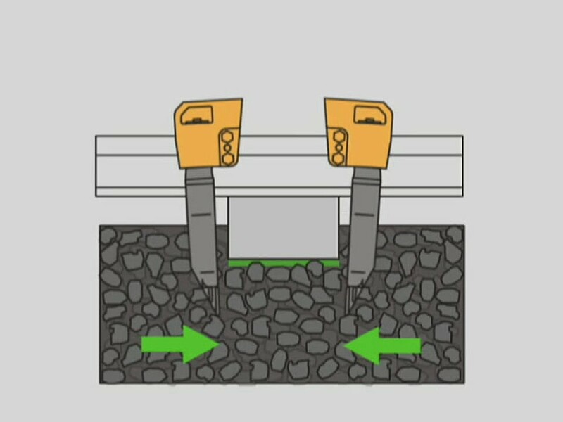
In order that the correction values determined in this way can be implemented, the existing ballast has to be supplemented in some places with new ballast. Depending on the correction procedure selected, the lifting and lining values of the machine give the necessary information about the desired vertical and horizontal change of position. The machine lifts the existing track skeleton and moves it in the desired direction. Under the track skeleton a free space is created which is filled in by the parallel compaction and consolidation process. There are various technologies on the market for this compaction process, two of which are described below. In this context the fundamental differences are first described, more detailed information is available on the manufacturer’s site.

Matisa tamping technology [1]
In 1980 the Swiss company Matisa developed the elliptic high frequency tamping procedure, a technology that differed from the linear tamping method that was widely used at that time. The elliptic movement of the tamping tines should, according to Matisa, simplify the penetration into the ballast because the individual ballast stones are displaced in a rotating motion. This fills the cavity under the sleeper caused by the lifting-lining process and creates a profound spatial consolidation. Originally the usual 35 Hz, was used[2].
New investigations in 2010, however, showed[3] that the tamping result could be improved by increasing the frequency to 42 Hz with an amplitude of 8 mm. In this case, the ballast was put into a "semi-viscous" state, which enabled an optimum distribution and compaction of the ballast bed.
Plasser & Theurer Tamping Procedure
In 1953, Franz Plasser and Josef Theurer developed the first hydraulic tamping machine. The use of hydraulics allowed the non-synchronous operation of tamping tines that were opposite one another. The uniform pressure on all tamping tines on the ballast guarantees the creation of a homogeneous support[4]. Studies[2]showed the importance of the choice of parameters (frequency and amplitude) on the durability of the tamping and the targeted consolidation (lifting of the track skeleton) to the ballast bed. Plasser & Theurer chose 35 Hz and an amplitude of 4 to 5 mm, a parameter set based on the testing performed by Fischer.
In combination with an adequate squeeze time these parameters are considered as a basis for the durability of the tamping. While the tamping tines are squeezed by means of the hydraulic cylinders (tamping force 10 to 12 kN), they are vibrated with a constant amplitude by a rotating eccentric shaft. In combination with a rotating mass this design allows stress peaks to be bridged and the tamping operation to be carried out in a short time. [5]
The basic parameters of the tamping procedure, have remained the same until this day over the many years of international experience. On new machines the speed regulation is used to reduce the flow behaviour at different frequencies in order to reduce the penetration resistance.

© Plasser & Theurer
The right choice of penetration depth
In both of these processes, it is important to ensure that the tamping depth of the tines is chosen sufficiently large depending on the selected track form (design height of the superstructure, rail, rail pads, fastenings and sleeper). If it is too low, it may be that the squeeze action damages the bottom edge of the sleeper. On the other hand, too large a tamping depth can lead to a low consolidation under the sleeper. The rules and regulations of DB Netz AG consider that 20 mm is the ideal distance between the upper edge of the tine plate and the lower side of the sleeper as the ideal tamping depth.

© Plasser & Theurer
You can find suitable specialist literature to the topic here:
The Basic Principles of Mechanised Track Maintenance

This book is dedicated to the many people involved in the day to day planning and performance of track maintenance activities. Providing a practical approach to everyday challenges in mechanised track maintenance, it is not just intended as a theoretical approach to the track system.
Railways aim at transporting people and freight safely, rapidly, regularly, comfortably and on time from one place to another. This book is directed to track infrastructure departments contributing to the above objective by ensuring the track infrastructure’s reliability, availability, maintainability and safety – denoted by the acronym RAMS. Regular, effective and affordable track maintenance enable RAMS to be achieved.
- [1] Grossniklaus, R.: Advances in Tamping Technology. AusRAIL. Adelaide, 2016.