Special designs
Expansion joint
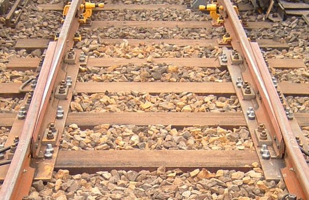
Movements (due to longitudinal forces) of the rail on bridges (e.g. due to braking and acceleration) and major temperature effects are compensated by dilatation joints (expansion joints).
An expansion joint consists of two jaw and tongue rails, which can move against each other. Expansion joints are generally fitted over moveable bridge bearings, in areas where there is mining subsidence, at the tunnel mouth or in steep sections of the line. Expansion joints are installed in order to absorb stresses (displacements) in the ballast bed caused by movements of the bridge frame.
The drag shoe ejector is used to eject drag shoes, if they are used when shunting to brake the wagon before it reaches the shunting department. The device consists of a wing rail and a tongue rail, with a gap of 10 mm between them. The wagon pushes the drag shoe forward allowing it to slide on the wing rail into a collecting basin. On the opposite rail a check rail is fitted which prevents the derailment of the train.
In order to obtain the most effective braking effect before ejecting the drag shoe, these are fitted at a certain distance (depending on weight and speed of the wagon) in front of the ejecting device. This task, however, is now generally done by electronically controlled track brakes.
Compensation rails
In the old jointed track and today in continuously welded rails the rail joints (fish-plated joints or welded joints) of the opposite rails should lie parallel to each other. As a result, the rails which lie in the curve are shorter on the inner side than on the outer side. This rail which is shorter than the parallel one is called the compensation rail. It is possible to work out by mathematical calculations the lengths of both rails and thus manufacture them to the exact length before installation.
Guide rail
Guide rails can be installed in curves with a radius of r = < 300 metres in order to relieve the outer rail of the curve. While running through this curve the wheel should be made to run on the inside of the guide rail and thus prevent wear and tear on the outer rail of the curve.
This rail must be fitted on the inner side of the track, if no rails with a minimum tensile strength of 880 N/mm² are present there. The distance to the normal inner curve rail should be 60 mm. Also an infeed or outfeed should be present at the beginning and end, so that the wheel is not derailed or does not climb up. The guide rails are not welded but connected together by fish plates in lengths of 15 metres, so that they can take the temperature and the track can creep.
Guard rail
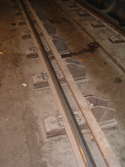
If the vehicle is derailed it should get the necessary support so that the wheel can be held on the rail or in the gauge. The distance between the guard rail and running rail is 80 mm. These guard rails are used on uneven bridge tracks, on layouts which are unusual and with longer transition lines with a steep slope to a gradient free track.
The guard rails serve as a derailment protection so that climbing up of the wheelset on the running rail is prevented, since the opposite wheel runs against the inner guard rail.
In the case of a tread width of approximately 135 mm and a groove width of 80 mm for the guard rail the wheel cannot derail. Guard rails are not welded together, but connected by fish-plates in lengths of about 15 m.
Guide Rail
A guide rail with a lead-in should continue to guide the vehicle in a derailment in the track groove of 180 mm, in order to prevent serious damage to buildings or even prevent crashing into bridges.
They are arranged parallel to the track and at a distance of 180 mm from the running rails on the inner sides of the track. They are even installed on bridges on both sides. In the case of a structure that is more than 50 metres long, vehicles derailed on the bridge cannot be protected before crashing. They are installed under structures to prevent bridge piers or other structures from damage in the event of a derailment.
The guide rail is installed over the structure to be protected with a length of the lead-in device of at least 10 m in front of and behind. These are not welded together and have a lead-in and a lead-out at the start and the finish.
Passende Fachliteratur zur Bahninfrastruktur finden Sie hier:
Designing Railways
This book presents the current state of the railway technology in Germany and also in Austria to a lesser extent. It looks forward to expected technical and legal developments and also contains valuable information on effective planning and approval procedures.
The authors are well-known experts in the railway sector and their expertise make this book an indispensable compendium on the subject of railway construction. The book is aimed at civil engineers and architects as well as students at the German-speaking technical universities and colleges. It provides all necessary information and tips, e.g., on line management, superstructure, railway bridge construction, earthworks, tunnel construction, railway crossings, container terminals, sound and vibration protection. As the railway system is an extremely complex technical system, there is also a description of the essential requirements, which are derived from other relevant fields, such as signalling, overhead lines and vehicle interface.
Best Practice in Track Maintenance, Vol 1 - Infrastructure Management
Infrastructure Management Volume 1 looks at aspects of infrastructure management with particular reference to the single European railway area. Based on best-practice examples from Central Europe, measures for the targeted retrofitting and improvement of the infrastructure maintenance of the existing network are presented. In many cases, infrastructure operators are faced with a generational change, which accelerates the process. Modern information and communication technology can simplify the comprehension and presentation of complex contexts. Modified approaches to asset management and life-cycle management enable implementation of the "transparent permanent way" or the "railway 4.0".


