Digital turnout diagnosis
In contrast to many other infrastructure components, the turnout is subject to continuous movements and loads in a wide variety of directions. Highly loaded points are changed over up to 170 times per day. Trouble-free turnout circulation and safe reaching of the end position are elementary prerequisites for reliable railway operations.
The turnouts are changed over by electric turnout drives and connected transmission rods. Especially drives, transmission linkages and locks at the turnout are critical points which often lead to restrictions of availability. If the current available at the turnout is no longer sufficient to change and lock the turnout in its position, no track can be provided for operation.
Two core elements form the prerequisite for a predictive system in the management of infrastructure facilities:
– In order to ensure high plant availability, it must be possible to record their current status remotely at any time, i.e. without the need for selective start-up/readout of the plants in the field.
– In addition to recording the status, it is also necessary to analyse the data, detect any deviation from the target status at an early stage and make the correct diagnosis for the cause – also remotely.
This is where the early warning system DIANA (diagnosis and analysis) of Deutsche Bahn AG, which covers all types of plants, comes into play.
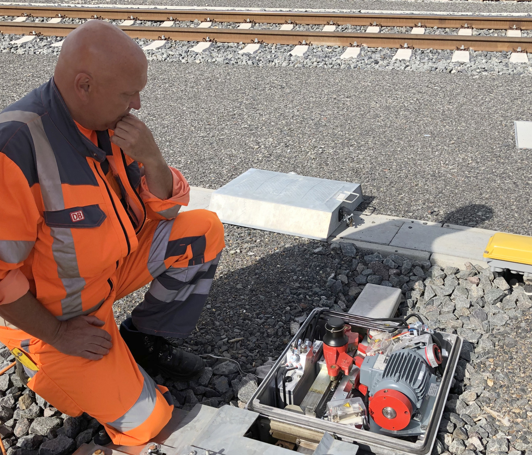
© DB AG/Max Zimmermann
Functionality
Sensors in the interlocking system monitor the current flow in the drive motors. The data analysis searches for conspicuous changes and indicates when maintenance is necessary, e.g. to prevent train delays and failures.
The starting point is a sensor, which is located on the power cable of the turnout motor. If the turnout is set for a train journey, the sensor measures the current required for this. The current is measured contactlessly and without feedback. The current curves are measured for each switching operation and sent to the analysis platform. On the platform, the data is analysed on the basis of parameters and user rules set individually for each turnout.
Decisive for the evaluation and analysis of the changeover movement is, in addition to the actual circulation phase, the unlocking and locking phase of the turnout tongue.
For the diagnosis three essential parameters are used at each drive:
– the switch-on time,
– the maximum required actuating current and
– a reference curve individually defined for each turnout.
The individuality of the curves of the setting currents of the turnouts results in particular from the design, size and location.
Using the calculation algorithms stored in DIANA, the individual measured parameters are compared with the parameters for each switchover process. The diagnostic messages are visible in the system and can be made available to the assigned users in parallel by e-mail or SMS. If the determined value deviates from the normal energy consumption of the motor, the maintenance staff will be activated. Based on the data, they can diagnose the extent of the malfunction at an early stage and what preventive repair work is necessary to avoid a defect. Reasons for the energy-consuming heavy operation of the turnout can be e.g. stones or ice, but also wear and tear and a lack of lubrication of the moving parts.
The diagnosis and analysis platform also receives data from sensors that monitor the sleeper position of turnouts that are travelled over at high speeds. The system monitors whether the switch sleepers sink too deeply into the ballast, as this can also cause failures.
Further development
By 2020, 28,000 existing railway turnouts throughout Germany have already been equipped with the new technology. In total, there are around 66,000 electric turnouts in the German rail network. In addition to the components of the turnouts, it is also planned to connect point heating systems, level crossings and interlockings themselves to the diagnostic platform with these sensors and to use them for predictive maintenance.
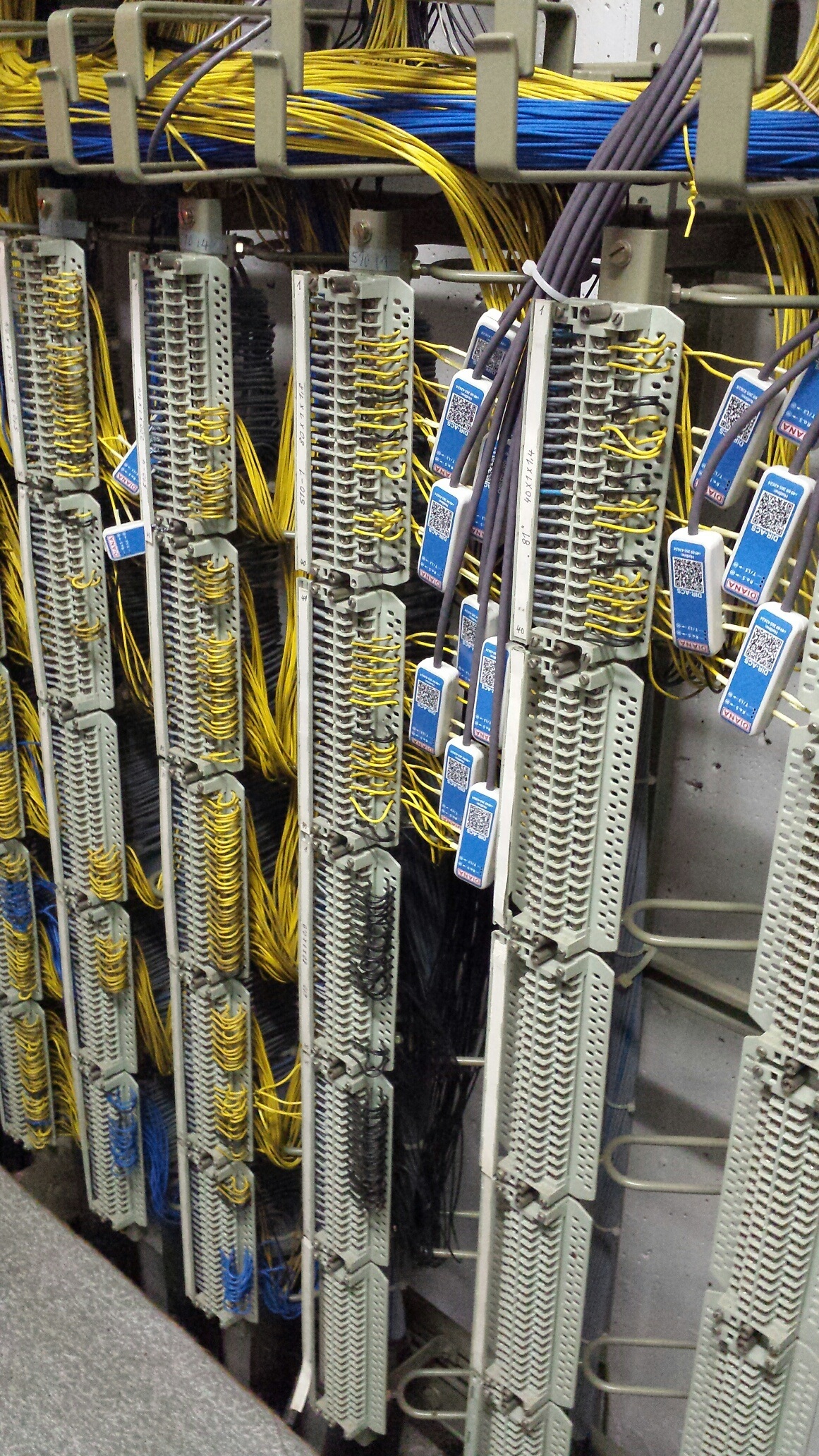
© DB AG/ Claudia Münchow
Recommended specialist books:
Rees, Dagmar, Digitalisierung in Mobilität und Verkehr
https://www.pmcmedia.com/en/all-titles/rail/262/digitization-in-mobility-and-transport
DB Netz AG (Ed.), Infrastrukturprojekte 2020 – Bauen für die starke Schiene
https://www.pmcmedia.com/neuerscheinungen/425/infrastrukturprojekte-2020